SINET 10
Fluid Flow Simulator
Advanced Features
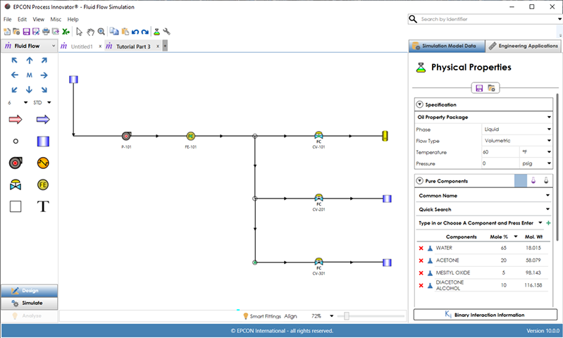
SINET Fluid Flow Simulator powered by EPCON’s Process Innovator simulation interface provides hydraulic modeling of pumps, miscellaneous equipment, control valves and flow meters for liquid or compressible gas systems with a common stream. Advanced features of SINET Fluid Flow Simulator include the following with a detailed explanation of each node and equipment type detailed below:
- Both Liquid and Gas systems can be modeled in the same Process Innovator interface.
- Design, Simulate and Analyze to determine root-cause flow and pressure problems in any size system.
- Size piping and process equipment such as pumps, heat exchangers, control valves, and flow meters
- Includes the AIChE DIPPR® pure component physical property database of over 2000 components.
- Patented interface with Smart Fittings™ to automate the entry of fittings and hand valves.
- Automated integration of gas density changes over long distance pipelines
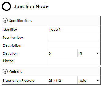
Junction Nodes
Junction nodes are nodes typically internal to the system through which all the flow entering into the node from a pipe (or pipes) leaves through a pipe (or pipes). The net flow of any node with two or more pipes connected is always zero since all incoming flows will equal all outgoing flows. Only elevation can be specified for Junction nodes other than its description. Extra Junction nodes may be added for displaying the pressure at a specific point in the system. Select the upstream or downstream pipe to display outlet or inlet static pressure at this point in the system since junction nodes only display stagnation pressure.
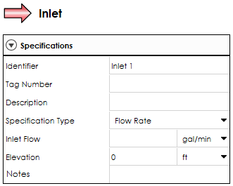
Inlet and Outlet Nodes
Inlet and Outlet nodes are used to represent flow entering or leaving the system being simulated. Inlet and Outlet nodes by default are used to specify inlet and outlet flows with the option to specify a pressure. If pressure is specified, their status as either being an Inlet or Outlet may change depending upon the results of the fluid flow simulation.
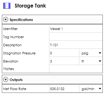
Vessel Nodes
Vessel nodes require the specification of stagnation pressure. The net flow in or out of the system is calculated and the direction of flow may change once the model results are displayed.
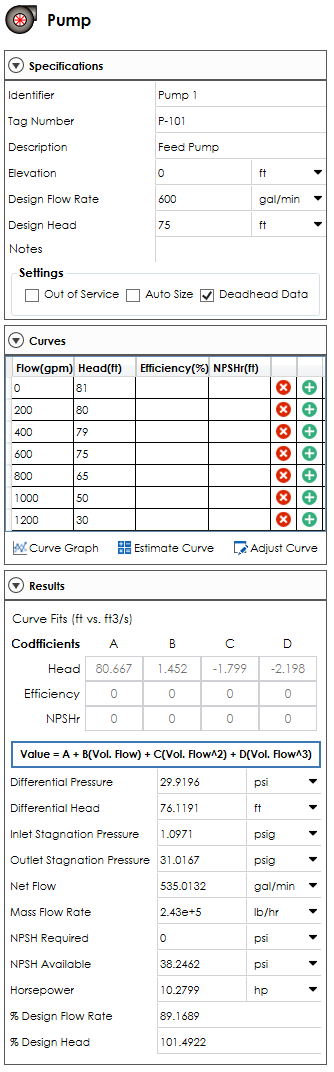
Pumps
Pumps are used for adding pressure to the system based on entered flow versus head pressure data (pump curve data). The pump curve can be estimated using the design flow and design head. A pump can also be auto sized to determine the head pressure required to meet a specified flow and placed anywhere in the system.
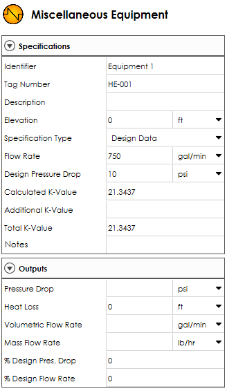
Miscellaneous Equipment
All miscellaneous equipment types are based on the entry of Design Flow and Design Pressure drop. Using this data, a k-value will be calculated to simulate operation at design flow and anywhere above and below this point.
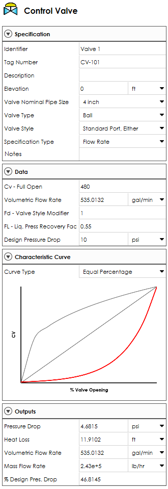
Control Valves
Valves can be specified as percent open, control flow, control downstream pressure or control upstream pressure. A generic control valve is the default symbol with optional symbols for globe control valve, ball control valve, butterfly control valve, let-down valve, manual valve and post indicating valve.
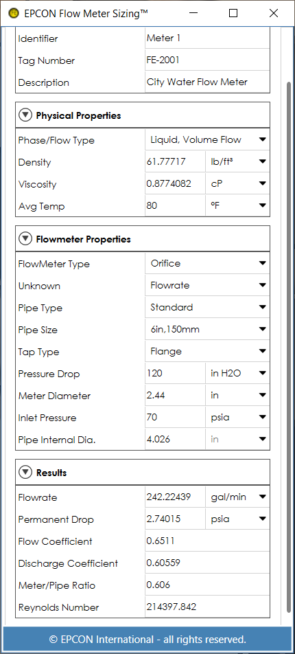
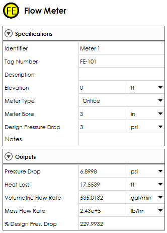
Flow Meters
Flow meters can be specified as orifice, venturi, or flow nozzle that provides rigorous computations for these types. If ‘other’ is selected, then the design flow and design pressure drop entries will be used to develop a k-value to accurately provide the pressure drop and design flow and scale well above or below the design point.
Equipment Sizing Applications
EPCON has been providing applications to size process equipment for over 30 years. The goal for each app is for quick and easy operation. Once you learn how to use one of these engineering apps, all of the others are very easy to load and use. These equipment sizing applications provide the ability to display multiple instances of calculations. Each input and output within a program instance allows for individual customization of units of measure in addition to the global selection of either English or Metric engineering units.
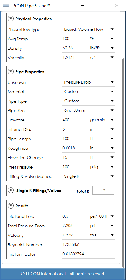
Pipeline Sizing determines the flow rate, pressure drop, or diameter for single phase flows in individual pipes. Load a selected pipe in the Process Innovator interface into this detailed sizing program with a single click. Calculate the pressure drop, flowrate or diameter for either liquid or gas pipes.
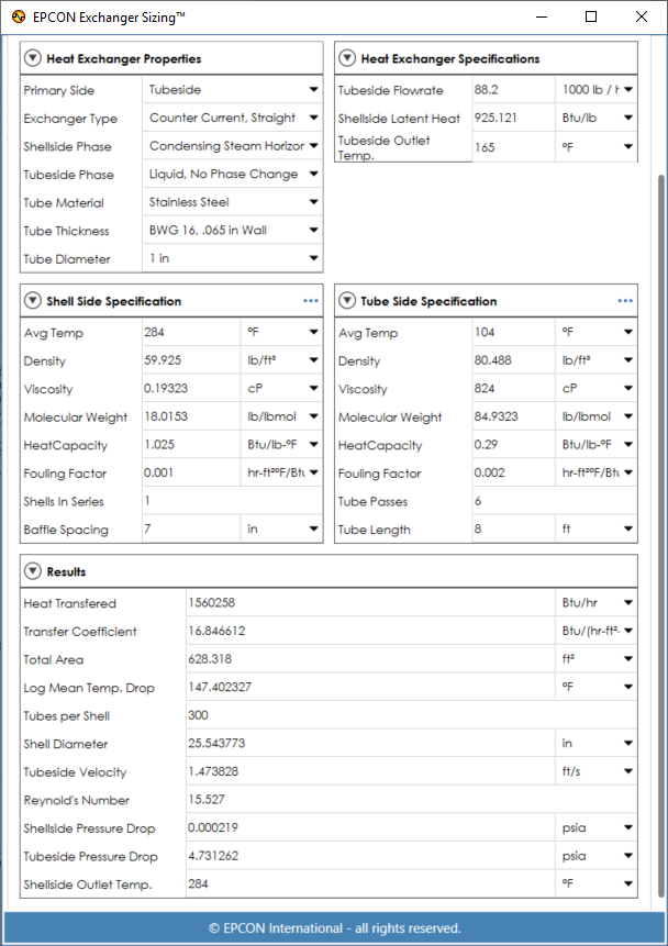
Heat Exchanger Sizing sizes Shell and Tube heat exchangers and can be used for any combination of liquid, gas, condensing, or boiling on either the shell or tube side. Accurate sizing can be done without supplying the thermal conductivity or heat transfer coefficient data.
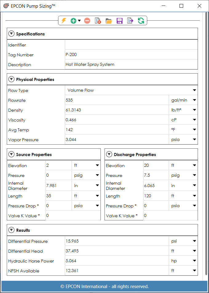
Pump Sizing determines the required pump differential head, hydraulic horsepower, and NPSH available of a pumping system with one suction pipe and one discharge pipe. The suction and discharge pipeline pressure drops are automatically calculated when the diameter and length are entered.
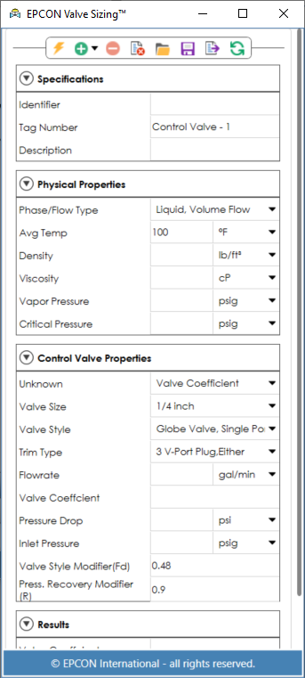
Control Valve Sizing sizes control valves for both gases and liquids. Either the pressure drop, the sizing coefficient, or the flow rate may be determined. The user may evaluate the effects of low versus high recovery valves and determine valve size required to meet a given process demand.
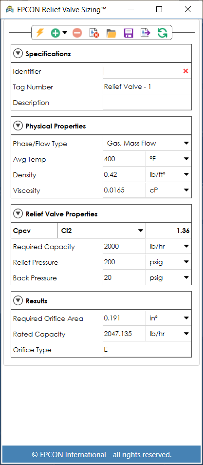
Relief Valve Sizing sizes relief valves for both gas and liquid duty. Based on the ASME pressure vessel codes (section VIII), this program provide a quick and accurate way to evaluate your relief valve needs.
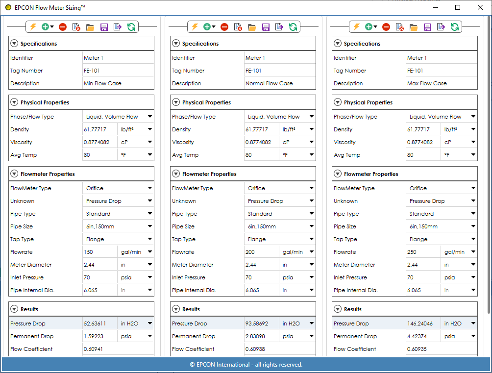
Flow Meter Sizing sizes orifice plates, venturi tubes, and flow nozzles for liquid and gas systems. The methods used are based on the Fluid Meters report published by ASME. The program can solve for pressure drop, orifice diameter, or flow rate.