PRV PRO
Relief Valve Analysis
Powerful Features
PRV PRO is based on published API and DIERS relief valve calculation methods using the THERMA PRO flash engine. It is the most mature and robust commercially available software for pressure relief valve analysis of non-reacting systems. Developed over the past 25 years with a rigorous flash, 2-phase flow, and relational database, nothing compares to its accuracy and ease of use. With PRV PRO, you can master pressure relief valve calculations with minimal training. Tree-view navigation is provided for entry of equipment, fluid stream and relief valve data. Once the required data is entered, the relief valve type and orifice size for the worse case scenario is determined and the inlet and outlet pipes are sized.
Sizing and Analysis Capabilities
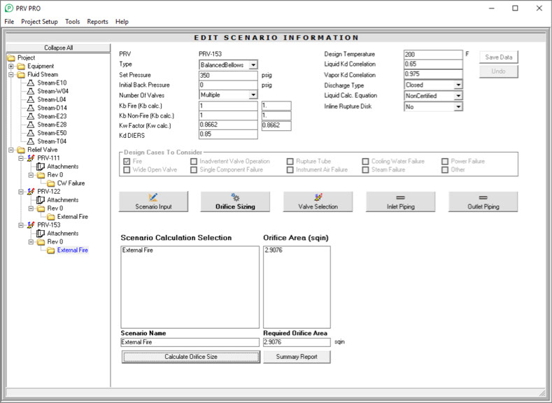
The PRV PRO™ pressure relief valve analysis program determines the relieving flowrate and the required size of a pressure relief valve orifice for a protected system. The program also sizes inlet/outlet lines based on maximum relieving flow and the selected valve. The user enters equipment data, fluid stream data and relief valve data to size the valve(s) and the inlet and outlet piping. The fluid conditions that describe each relieving case are entered into the PRV PRO database. The program calculates an orifice size based on the worst case scenario and then selects standard API valve(s) based on set pressure, design or maximum flow temperature and the largest calculated area. Inlet and outlet pipeline pressure drop is calculated based on pipe length, size, and fittings for liquid, gas or 2-phase pressure drop.
Database Documentation
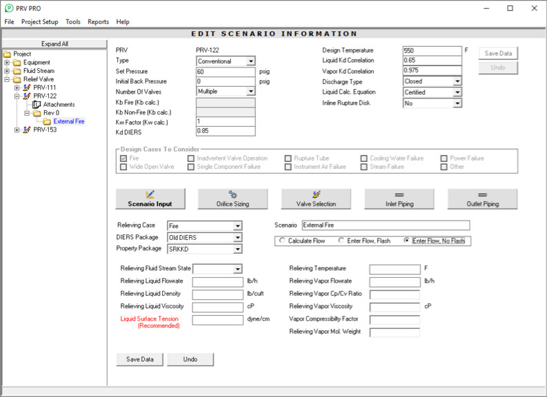
Once the relief valve calculation is completed (“Issued”), the calculations are documented in a SQL database for future reference and relevant data from the calculation is used to create Excel and Text outputs. Multiple relieving cases may be considered to determine the largest orifice size necessary for pressure protection. Detailed calculations to determine the relieving flowrate & phase condition are provided for Fire, Inadvertent Valve Operation and Ruptured Tube cases. All other cases can be run by specifying flowrate and phase condition or from the phase condition determined by the integrated, rigorous 3-phase flash engine (user entry of the relieving flowrate required for these cases).
Relief Scenarios
Excel templates are provided for calculating the relieving flow of other common scenarios which can be attached to each relieving case and saved to the database to document these calculations. Any number of custom Excel templates can be included in PRV PRO to allow existing computational approaches to be used, as well.
- Fire Case – robust calculation of gas expansion and liquid vaporization to determine flowrate or manual entry of known flow with or without flashing.
- Inadvertent Valve Operation – robust calculation of flowrate and manual entry of flowrate with or without computation of phase condition.
- Ruptured Tube – robust calculation of flowrate and manual entry of flowrate with or without computation of phase condition.
- Power Failure – manual entry of flowrate with or without computation of phase condition.
- Cooling Water Failure – manual entry of flowrate with or without computation of phase condition.
- Instrument Air Failure – manual entry of flowrate with or without computation of phase condition.
- Steam Failure – manual entry of flowrate with or without computation of phase condition.
- Single Component Failure – manual entry of flowrate with or without computation of phase condition.
- Other – manual entry of flowrate with or without computation of phase condition for any other type of failure not specifically addressed above.
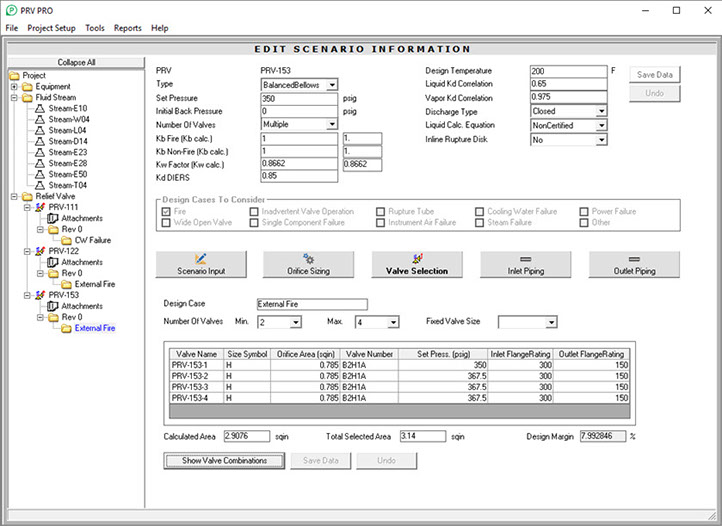
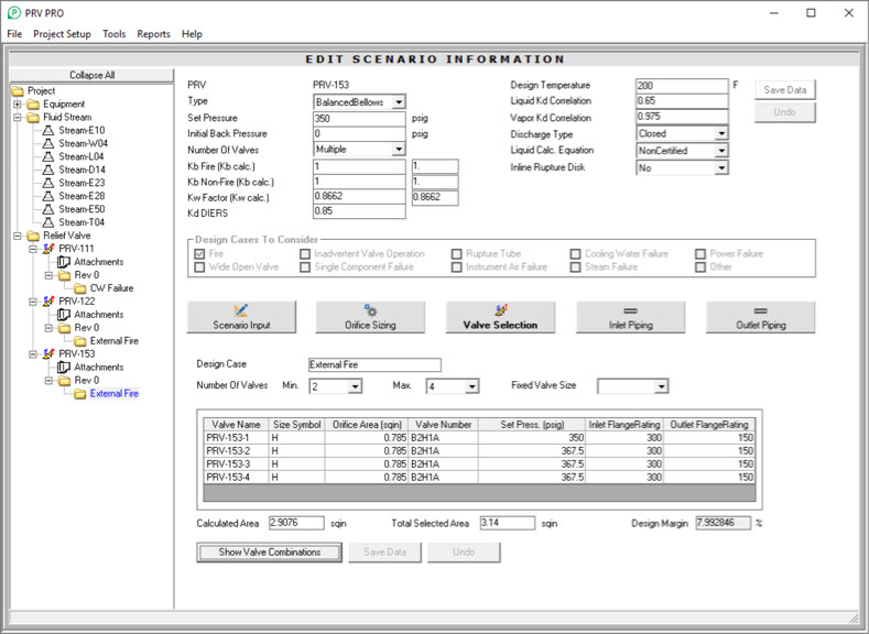
Valve Selection Data Entry
This allows the user to select standard API valves and corresponding internal company designation valve numbers to meet the minimum required orifice area. The user can select standard API valve(s) by clicking on the Show Valve Combinations button or by manually entering desired selections. Non-standard valves, e.g. pilot or threaded valves, can be specified by manually entering desired specifications. The program automatically selects a corresponding valve number for each selected valve. An asterisk beside the valve number indicates there are additional choices which can be displayed. The program ensures that the total selected valve orifice area is greater than the calculated required orifice area. If multiple valves are required due to a large required orifice size versus a single valve, the program requires that the Orifice Sizing step be repeated before the various valve options can be displayed to ensure proper calculation according to recommended API standard procedures.
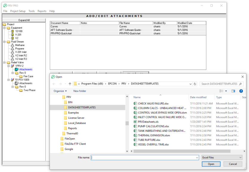
Excel Templates
PRV PRO includes Excel templates to calculate the relief flow for many common scenarios. These can be accessed by selecting the Attachment icon for any relief valve and selecting the Templates button. These templates include check valve failure, column unbalanced heat duty, control valve bypass failure, inlet control valve failure, pump calculations, tank in-breathing and out-breathing, thermal expansion, tube rupture, and vessel overfill time. Custom Excel templates previously developed can be used and included in any scenario and documented in the SQL database.
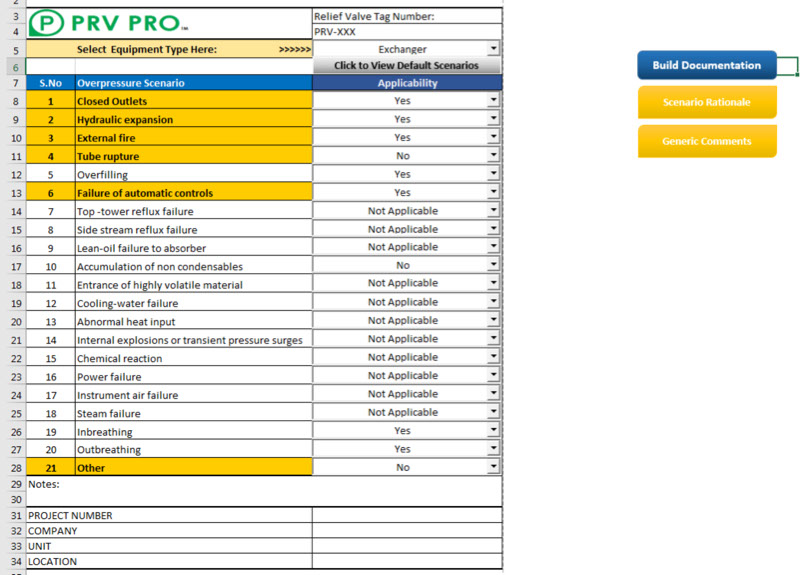
Documentation Builder
The “Documentation Builder” template automates the process of writing overpressure scenario rationale. Upon selecting the equipment type and scenario applicability, the program utilizes predefined generic text to automatically generate the documentation.