EPCON Process Innovator
Design – Simulate – Analyze
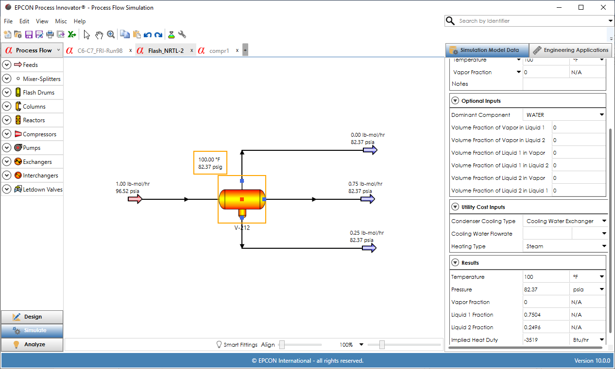
The EPCON Process Innovator® graphical user interface allows for the design, simulation, and analysis of process and utility systems. Fluid Flow Simulation provides hydraulic modeling of single phase, single stream branched and looped piping systems. Process Flow Simulation provides hydraulic analysis of any stream (liquid, gas or 2-phase flow) and simulation of unit operations including columns, reactors, flash drums, compressors, turbines, pumps, heat exchangers, interchangers and let down valves.
Design – Simulate – Analyze
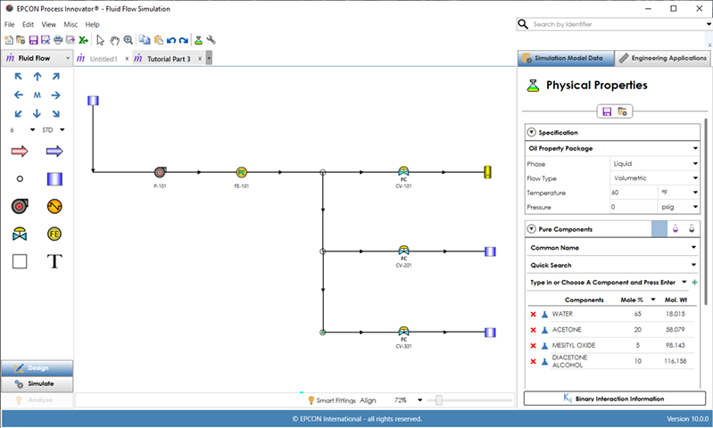
In the Process Innovator GUI, there are 3 steps in modeling – Design, Simulate and Analyze accessed from navigation buttons at the bottom of the Left Hand Panel (LHP). In Design mode, a PFD of a process or utility system is drawn by dragging and dropping equipment and unit operations on the drawing canvas and connecting their ports with pipes or streams. Speed Draw creates a pipe or stream and an equipment or unit operation at the same time in the direction selected.
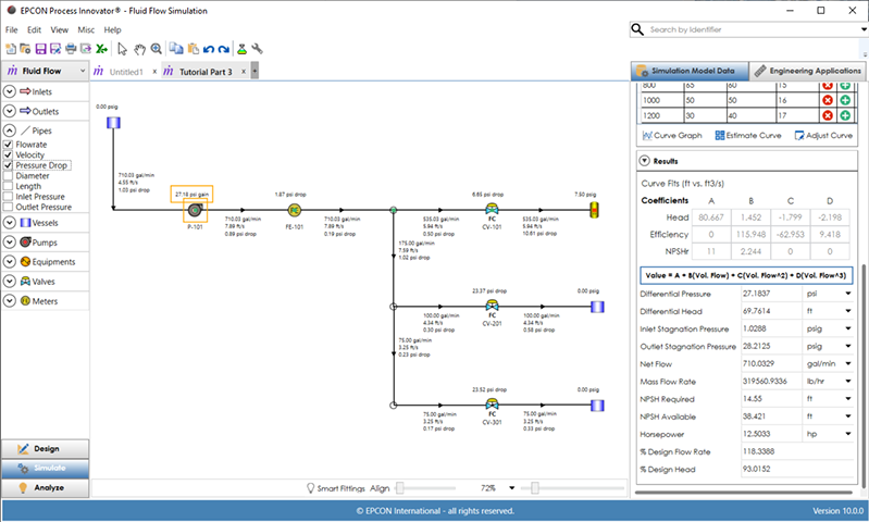
In the Simulate mode, the model results are displayed in a few seconds using EPCON’s advanced simulation engines. The Simulate mode allows for review of input and output results on the drawing canvas as specified on the LHP. Clicking any equipment, unit operation, pipe or stream displays input and output data in the right hand panel (RHP).
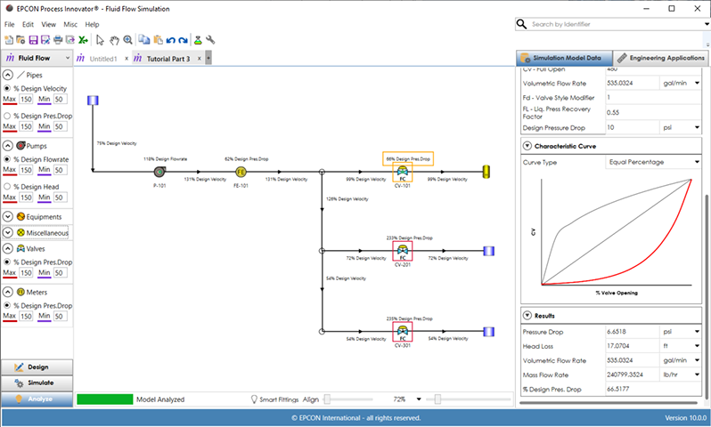
For Fluid Flow Simulation, Analyze provides a detailed diagnostic of what equipment and pipes in the PFD are above or below specified minimum and maximum design specifications. This helps identify the root-cause problems of flow and pressure drop. For Process Flow Simulation, the Analyze mode displays the phase type of each stream which is highlighted by a specific color.
Property Packages
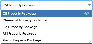
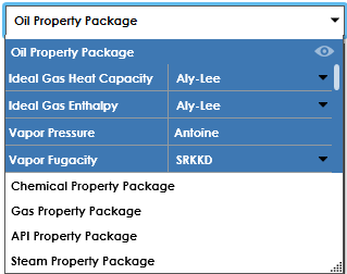
The property packages used in the Process Innovator set all of the property methods for a specific process type based on API recommended best practices in industry. For the Oil, Chemical and Gas processing industries, these named property packages are recommended. The API property package provides agreement with the API Tech Data Book and the Steam property package is for use in simulation of steam systems with multiple pressure levels, let down valves, and turbines. View optional property method choices for each property package.
Pure Components
Over 2000 pure components are available from the AIChE DIPPR® Database for specifying the components in the simulation (DIPPR is a registered trademark of AIChE and is used with permission).
Pseudo Components
The pseudo component option allows for entry of one pseudo component at a time by specifying a specific or API gravity and boiling point (molecular weight optional). To generate a series of components related to an assay, enter the assay data.
Binary Interaction Information
A databank of accurate PR, SRK-KD and NRTL parameters is included that is automatically selected for component pairs. Use the View Binary Parameters button to display coverage of binary pairs. Experimental VLE data to create custom binary parameters for any system of interest is available from DDBST (www.ddbst.de).
Pipe Data Entry
Pipes are used for placing resistances in the system such as pipe length, fittings, hand valves, etc. in Fluid Flow Simulations and optionally pipe data can be entered for streams in Process Flow Simulations.
Smart Fittings
Selection of Smart Fittings™ on the status bar at the bottom of the screen will automate the population of fittings, hand valves, and reducers using standard piping practices. Smart Fittings will automatically enter fittings and hand valves for every pipe in the system when selected at the bottom of the screen and the model is simulated.
