CHEMPRO 10
Chemical Process Engineering Suite
Powerful Features
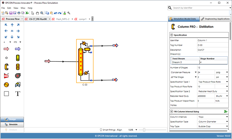
CHEMPRO Engineering Suite includes all of the features of SiNET’s Fluid Flow Simulator and adds Process Flow Simulation™ for the analysis of process systems along with THERMA Pro. The EPCON Process Innovator® simulation interface provides efficient design, simulation, and analysis of Process Flow Simulation with the same interface design and ease of use as Fluid Flow Simulation in SINET. There are fifteen unit operations available for creating a process flow diagram (PFD). Once stream and unit operation data is entered, the PFD can then be simulated to predict unit operation performance and optionally determine pressure drops for liquid, gas and 2-phase streams when pipe data is entered on streams. Property Packages available in CHEMPRO contain all of the property methods for a specific process type based on recommended best practices in industry (Oil, Gas and Chemical property packages are most widely used) and can be customized. A summary of each stream and unit operation type are shown in detail below.
Feed Streams
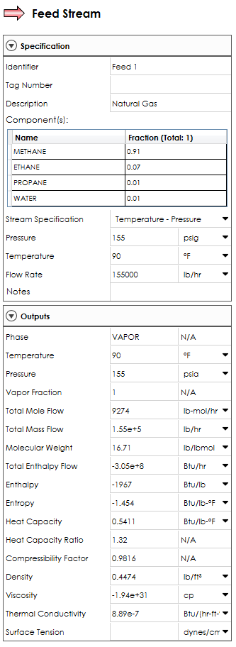
A feed stream requires entry of the stream composition from the components selected in the Physical Properties along with flow rate, temperature and pressure. Flow Type can be specified as mole, mass or volumetric in the dropdown list (Mole is default). A dominant component can be specified for a 3-phase flash.
Product Streams
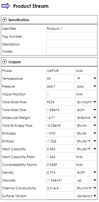
For Product streams, no input data is required since the composition, phase, flow, temperature, pressure and other physical properties will all be calculated.
Stream Pipe Data
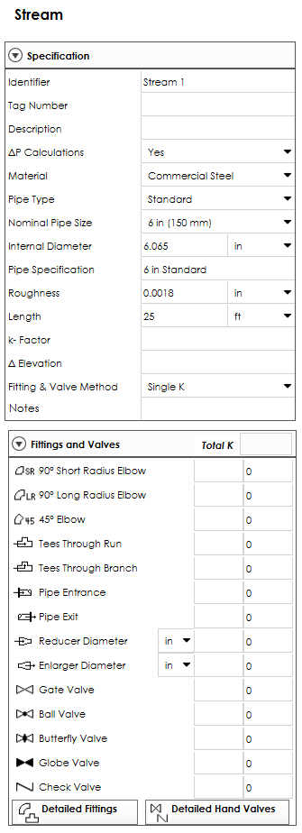
Stream pipe data can be entered by selecting a stream line between a feed, product or unit operation. Selecting ‘∆P Calculations = Yes’ will allow entry of pipe data that is required including material, pipe type, nominal pipe size, internal diameter, pipe specification, roughness and length. Then the pressure drop in streams with pipe data will be displayed in the stream output data. The phase of the stream is first determined and then the appropriate pressure drop correlation (liquid, gas, or 2-phase) is used.
Mixer/Splitter
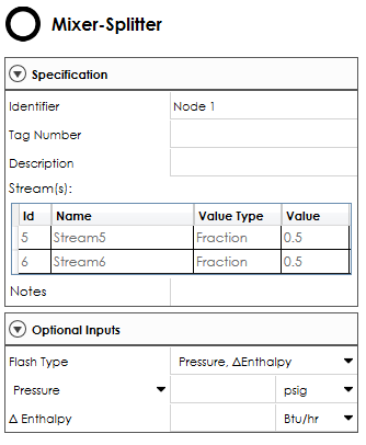
A mixture/splitter icon is represented by a small circle with all other unit operations represented by a specific unit operation type or alternative symbol. Mixer/Splitters are internal to the system through which all the flow entering into the node from a stream(s) leaves through a stream(s). A mixer (only one outlet), does not need any data input while splitters require input of flow splits.
Flash Vessel
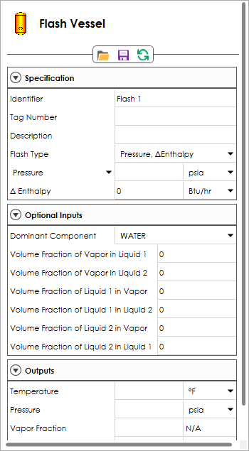
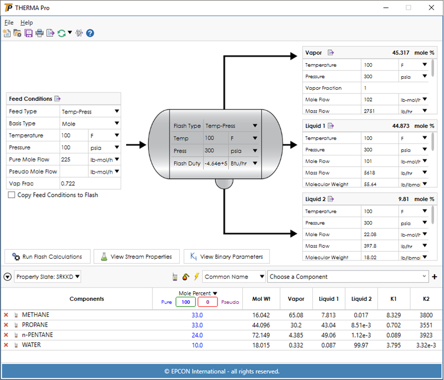
For a 2-phase flash, the top outlet will contain the vapor product from the flash and the bottom outlet will contain the liquid. The 3-phase flash allows for three outlet streams to be specified. The top outlet will contain the vapor product, the side outlet will contain the first liquid phase, and the bottom outlet will contain the second liquid (aqueous) phase if present.
Column
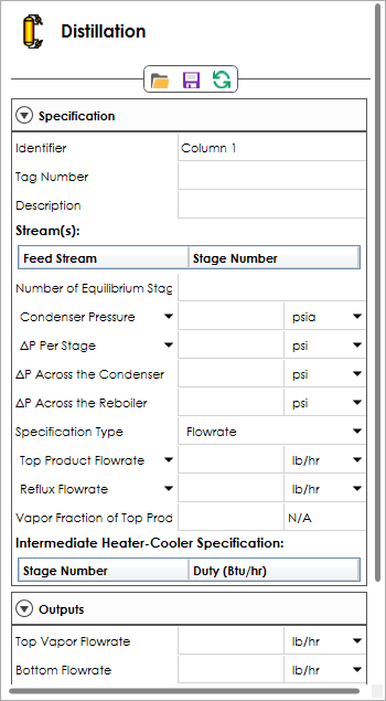
A column can be simulated with all the loads fixed, (rating calculation), or to meet certain performance specifications for distillation, refluxed stripper, reboiled absorber and absorber/stripper unit operations. Condenser duty, condenser temperature, or fraction of vapor product is used to determine the type of condenser. A good estimated column temperature profile is automatically generated based on the feed stream conditions.
Reactor
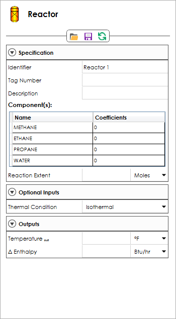
The Reactor Unit Operation is designed to simulate a reaction equation where ‘Reactants’ are combined to create ‘Products’ according to a stoichiometric relationship. The Reactor Unit Operation will then remove the Reactants and create the Products according to the Stoichiometric Coefficients entered.
Compressor
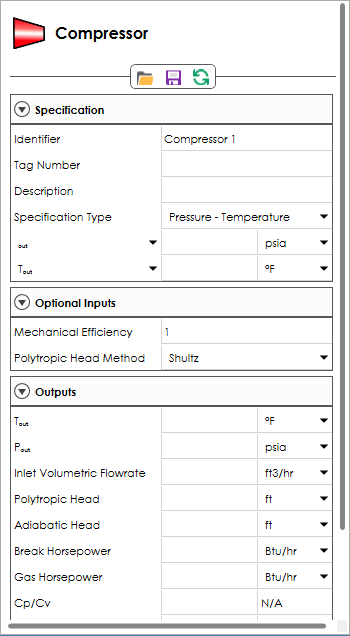
The Compressor Unit Operation provide both adiabatic and polytropic compressor and expander calculations – including liquid entropy and 3-phase mixture calculations for the inlet and outlet streams. The discharge pressure must be specified with one other input specification (discharge temperature, heat duty, compressor power, compressor head, pressure differential, inlet to outlet pressure differential and polytropic efficiency).
Exchanger
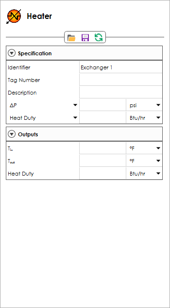
The Exchanger Unit Operations provide a Heater/Cooler for a single process stream and a Heat Exchanger for 2 streams to exchange heat between a hot and cold process stream (interchanger). Only one of the following heat transfer specifications needs to be specified for each side of an exchanger: heat duty, outlet temperature, differential temperature, vapor fraction, subcooling, superheating, minimum temperature approach (interchangers only).
Pump
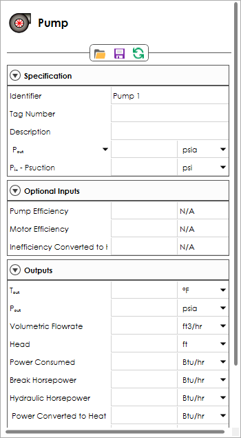
The Pump Unit Operation simulates a single stage of pumping and develops and tabulates the general process-related design data needed for specification of centrifugal pumps including estimates of power requirements. Pump and motor efficiencies may be provided by the user, otherwise they default to estimated values.
Let-Down Valve
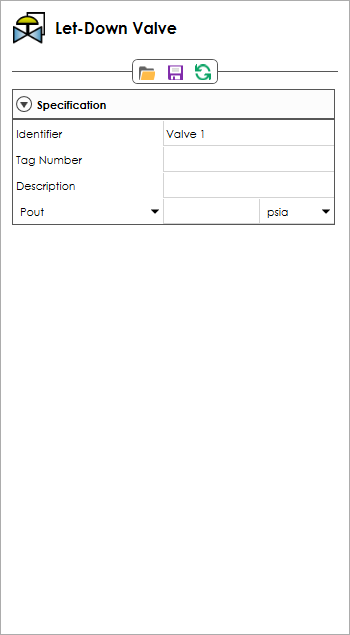
The Let-Down Valve Unit Operation is a simplification of the flash unit operation that allows only one inlet and one outlet and performing only a pressure – enthalpy (PH) flash. Entry of the outlet pressure or pressure drop is required.
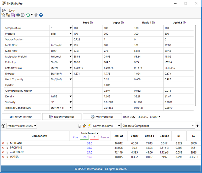
THERMA Pro™ included in CHEMPRO performs 2-phase and 3-phase flash calculations for mixtures of pure and/or pseudo-components. The physical properties of pure or pseudo-components and their mixtures are based on DIPPR and API correlations. The three-phase flash engine enables the user to predict phase splits involving a vapor and two liquid phases, wherein the second liquid phase (if present) is an aqueous phase. The graphical image on the main screen automatically changes from a vertical to horizontal drum when a second liquid phase is present as shown below.
Pseudo Components, SRK and NRTL parameters
Pseudo components can also be automatically generated by entering either a D86, D2887, or TBP crude assay along with the API or Specific Gravity. The generated pseudo components and calculated mole percentages are placed into the flash so that only the stream properties need to be entered to determine the phase split and properties of each phase. A databank of accurate SRK-KD and NRTL parameters is included that is automatically selected for component pairs -providing high quality 2-phase and 3-phase flash results. Use the View Binary Parameters button to display coverage of binary pairs. Experimental VLE data to create custom binary parameters for any system of interest is available from DDBST (www.ddbst.de).
